
Building the Pro Fusion SC 4×4 is a simple process and went fairly smoothly. I did take a couple of notes along the way on a few steps that I felt needed clarification. I did speak to the gentleman that helped write the assembly manual about these steps and he assured me that on future versions of the manual those points would be addressed.
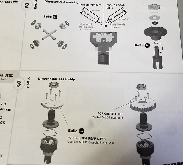
Step 2: You will need diff oil for this step as it is not included in the kit. I used 7,000CST for the front, 500,000CST for the center and 5,000CST for the rear. This is where I am going to start for dirt oval use and will go from there. Once the 2.8’s are on I will most likely go up in the front and rear to deal with the extra rotational mass. The manual recommends 500,000CST for the center diff but shows grease for the front and rear.
Page 21 of the manual states that “when using 1:8 power systems with 4s lipo power, you may find that the center diff is sending too much power to the front wheels when the truck wheelies. To provide more balanced wheel speed front to rear with extreme power systems, use heavier diff fluid in the center diff.” There is no recommendation as to the front and rear diffs however.
Step 3: When tightening the screws that hold the ring gear (or spur) to the diff case check to see if the gears are binding when the screws are fully seated. I had to back all of mine out by 1/2 turn to keep the gears from locking together under the stress. Once the screws were loosened slightly the diff functioned as it should, and was quite smooth I might add.
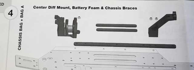
Step 4: When installing the rear chassis brace to the chassis and steel spine insert use the rearmost of the three countersunk holes in the chassis. The front screw hole is for the battery strap mount that is installed later.
Step 6: The upgraded snap ring for the pinion shaft can be installed without snap ring pliers but it is much easier with the correct tool. Alternatively, you can install the circlip that came standard with the Pro-MT as it is also included in the box. I used a pair of needle-nose pliers to install one of the snap rings and bought the proper tool before tackling the other. The tool reduced the time of installation from about 10 minutes to less than 15 seconds.
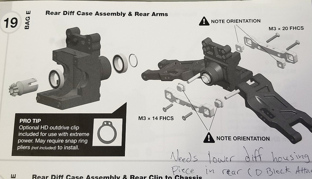
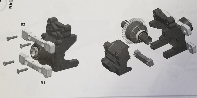
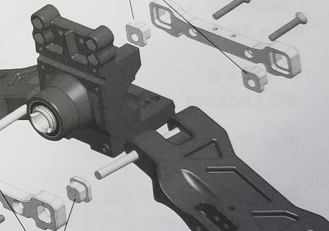
Step 7: Take note of the plastic piece that goes between the diff case and the suspension block. It is shown in this step as to where it goes but is shown already installed in the rear assembly in step 19.
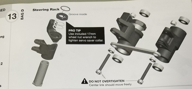
Step 13: When assembling the upper arm of the bellcrank/servo-saver to the lower portion, use a small amount of silicone adhesive to hold a 3mm lock nut in the under side of the arm. The linkage from the servo horn to the bellcrank will be installed here later and by installing the nut now it is much more accessible. I used one of the center diff cover screws to pull the nut up into place and then removed the screw leaving the nut where it will be needed later (the nut is shown in step 44).
Step 14: The steering bellcrank access plugs that are installed here can be found on the plastic parts tree from bag B.
Step 19: This is where the lower diff case piece that was discussed earlier comes into play. The order of assembly is: C block, diff housing, diff cover, lower plastic piece, and then the D block.
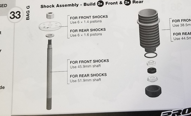
Step 33: When removing the plastic pieces for the lower shock cartridge ensure there is no flashing left after removing the pieces from the parts sprue. This is also a good time to lube the o-rings and ensure that everything operates smoothly before adding oil to the shock body.
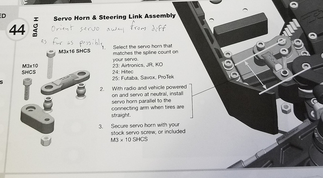
Step 44: When installing the M3x16 SHCS from the top side of the bellcrank, go slowly so as to not push the locknut that was installed earlier back out the bottom. There is not much room to work here since the side guard is installed. Pro-line offers an optional aluminum bellcrank arm, part #6318-03, that is threaded for M3 and does not require the use of the locknut.
Finally, while not a build tip but a maintenance helper, when removing the center diff for tuning or gear replacement remove the upper chassis plate first to allow more access to the front-center driveshaft. Without removing this piece it is a very tight space to work in and can be difficult to re-install the shaft. When doing it this way you can remove the center diff along with the center driveshafts without having to remove either the front or rear assemblies. It is only (4) M3 SHCS’s to remove the upper deck and doing so can save a lot of time. Don’t forget to thread lock the two forward screws that attach to the upper B block when re-assembling this piece.